

Credits for this article and images VertDude, first appeared on instructables.com
I wanted to build this heat exchanger to reclaim some of the heat that is lost up the chimney of my wood stove. I use the wood stove to heat my workshop during the winter months . I have seen heat exchanger units available in stores for around $160. Since I’m cheap, and I hate to pay money for things that I think I can build myself, I set out to create my own heat exchanger.
Step 1: Materials and Tools Used
Materials
- 2- 12″ x 12″ pieces of 19 gauge sheet metal
- 8- 1-1/4″ diameter thin wall steel pipe pieces 11-1/4″ long ( I used Galvanized top rail from chain link fence)
- 1- 2-1/2″ diameter thin wall steel pipe 11-1/4″ long ( I used Galvanized fence post)
- 1- 5 gallon steel bucket , the type that Tar, Asphalt roof coating or Driveway Coating come in.
- 2- 6″ diameter black steel stove pipe unions
- 1 -Can of High Temp Stove Paint
- 1-Tube of High-Temp Fireplace Cement
Tools I used
- MIG Welder
- Bandsaw
- Chopsaw
- Bench Grinder
- Angle Grinder
- Rotary Tool
- Tin Snips
- Various Drill bits
- 1-3/8 ” diameter Knockout Punch
Step 2: Preparing the Steel Pipes


I used left over pieces of galvanized fence posts and top rail for the steel exchanger pipes. I cut 8 pieces of 1-1/4″ pipe to 11-1/4″ in length. One piece of 2-1/2″ pipe was also cut to 11-1/4″ in length. After the pieces were cut , I removed any remaining burrs from the inside of the pipes. Burrs left behind will impede the air flowing through the unit.
The fence pipes that I used were Galvanized. The Zinc coating on the pipes needs to be removed before the pieces can be welded safely. Breathing the fumes from burning Zinc can cause illness. Usually I would use a grinder to remove the Zinc only in the weld area. Since this thing is going to be pumping air into my work space, I wanted to be sure and remove all the Zinc to be on the safe side. The easiest way I could come up with was to use Muriatic Acid. I put all the pipe pieces in a bucket with enough water to cover them all, about 2 gallons. Then I poured in about 2 cups of Muriatic Acid. I left the pipes to soak outdoors. After about 2 hours all of the Zinc coating had lifted off the steel and was floating around the top of the bucket. I rinsed the pipes thoroughly with water and dried them off. I neutralized the remaining acid solution with a box of Baking Soda before discarding it.
*Note about Muriatic Acid*
Use extreme caution when handling Muriatic Acid. Acid can burn the skin and severly damage the eyes. Wear rubber gloves and eye protection at all times when handling acids.
Muriatic Acid is a powerful acid used by cement workers to clean concrete from tools and such, it is also added, in diluted solutions, to swimming pools to adjust the P.H. levels. You can purchase Muriatic Acid at most home centers and Hardware stores for about $8 per gallon.
Step 3: Preparing the End Caps


I started by laying out the pipe locations on the 12′ x 12″ pieces of sheet metal. I first located the center of the piece. Then laid out 8 center points for the pipes equidistant around a 3-3/4″ diameter circle. The holes for the pipes needs to be 1-3/8″ diameter. On the prototype version I drilled the holes with a step drill, then ground them to their final size with a Rotary tool with a carbide cutter bit installed.
Click HERE to Get the World’s Smallest Battery, That Powers Your House For More Than 2 Days!
This took a long time and was not much fun at all. This time I used an electricians Knock Out punch. I was able to borrow one from a friend that was exactly the size I needed. The K.O. punch requires a 3/4″ hole in the metal to be able to be inserted. I first drilled a small pilot hole in each location using a center drill for accuracy. Next I drilled the holes out to 1/2″ diameter. Finally, I used a 3/4″ drill bit to achieve the final size.
To use the K.O. punch, the circle cutting die is un-threaded off of the shaft. The shaft is then inserted through the 3/4″ hole previously drilled in the work piece. The bolt is then tightened, pulling the cutting die through the sheet metal , creating a perfect hole. I used a pneumatic impact gun to tighten the K.O punch and speed things up.
Next, I cut the outside shape of the end caps. To do this, I needed to determine the diameter of the bucket that I was using for the housing of the heat exchanger. My bucket was tapered , so one end of the the unit has a 11-1/4″ diameter and the other end is 10-1/2″ diameter. To cut the end cap in a nearly perfect circle , I used a vertical band saw. I drilled a 1/8″ diameter hole in the band saw table the distance away from the blade equal to the radius of the circle desired. I also drilled a 1/8″ hole in the center point of the end caps. I then inserted a 1/8″ steel pin through the hole in the sheet metal, into the table of the band saw. Before I started cutting the circle, I had to trim the sheet metal in one spot to allow a location for the band saw blade to begin cutting. Now insert the pin through both holes, turn on the saw and rotate the sheet metal around the center pin to cut a circle.
Finally , I cut the 2-3/8″ center hole. To do this, I drilled a series of 5/16″ diameter holes around the circumference of the circle. Then I used a Rotary tool and carbide cutter to achieve the final shape .
Step 4: Assembling Heat Exchanger Core


Now it is time to assemble the heat exchanger core. I made a Jig to aid in holding the pipes in place while I’m welding them.To make the Jig, I laid out the same hole pattern as the end caps on a piece of 3/4″ plywood. I used a 1-3/8″ diameter Forestner bit, in a drill press, to drill a 1/4″ deep hole at each location. I set the depth stop on the drill press to assure that all of the holes are the same depth. The Forestner bit bores a flat bottomed hole allowing the pipes to stand straight up.
I started assembly by aligning an end cap over the wooden assembly jig. Then I inserted the first pipe section, held it in place with a magnetic welding clamp and welded a series of tacks to secure it in place. I made sure to check the squareness of the pipe several times while tack welding it in place. These tack welds will be on the inside of the heat exchanger when completed. I continued welding the other 7 pipes into position in the same manner. Once all 8 1-3/8″ pipes are in place, the assembly was removed from the wooden jig. Next I aligned the opposite end cap on the wooden jig, then carefully inserted the opposite ends of the asssembly into the jig. Again I made sure the pipes were perpendicular to the end caps and tack welded them in place. I then removed the assembly from the jig and welded a bead around the entire circumference of each pipe on the outside surface of the end caps. The final step was installing the center, 2-1/2″ diameter, pipe. I did not use the jig for this step, instead I held it in place while I tacked it in.
Step 5: Preparing the Housing (Bucket)


When I originally began to build the first prototype, I arranged the exchanger pipes in a rectangular pattern. I was planning on building the outer housing out of sheet metal, in a box shape. Then I had the idea to use a metal bucket. Perfect, it comes pre-made, and the round shape will help with the flow of the chimney. Now to find a bucket. I used an Asphalt Roofing Cement bucket. First I had to clean all of the cement out. To do this I first sloshed some mineral spirits around the inside of the bucket. This removed most of the roofing cement that was still wet. To remove the dried cement I decided the easiest way would be to burn it out. I started a fire in my outdoor fire pit, poked some holes in the bottom of the bucket, and placed the bucket upside down on the fire. I let the bucket burn for about 20 minutes. The previously hardened roofing cement was reduced to ash and could be removed with a wire brush. Once the bucket was cleaned up, I used an Angle grinder with a fiber cut-off wheel installed to cut the bottom of the bucket off.
Step 6: Installing Chimney Inlet and Outlets


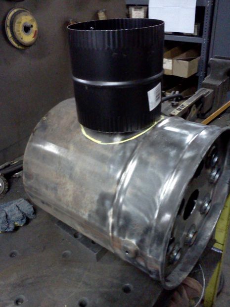


The chimney inlet and outlet are fabricated out of 6″ stove pipe unions. I purchased them for $7 each. I inserted the heat exchanger into the bucket while aligning and laying out inlet/outlet locations. Without the exchanger inserted, the bucket becomes oval in shape. The first thing I did is get the bucket propped up level. The bucket I used was tapered at the bottom , so I had to set it up on some shims. I also used the brackets that held the buckets handle in place to aid in alignment. I was able to measure up from the table to the brackets to verify that both sides were equal distance. This is important when you prepare to locate the outlet on the EXACT opposite side of the bucket, so that the unit will be properly aligned when installed in the chimney pipe..
Once the bucket was all set up good, I was able to continue laying out the inlet/outlet hole locations. This was an eyeball procedure for me. I set the union on the bucket and centered it by eye. Both the union and the bucket have a bead/rib rolled around them for added rigidity. I located the union so that its bead would contact the bead on the bucket. This area is more rigid than the rest of the bucket making it a good location for welding. the stove pipe unions are not exactly round. They have a flat side where the seam is. I was sure to keep the seam in the same position while fitting the unions. When I was satisfied with the location of the union, I used a paint marker held tightly to the union to mark the location. I used tin snips to cut out the opening, trimming carefully to try and make to hole just large enough to allow the union to fit as tight as possible. Once I got a good fit, I slid the union into the bucket, then used a paint market to draw a line around the perimeter of the union.
This Timeless Collection of Forgotten Wisdom Will Help You Survive!
Next I removed the pipe union from the bucket and offset the line I just transferred by about an inch. I then used tin snips to cut the union to length, cutting on the second offset line. After the union has been cut to length, I made a series of cuts perpendicular to the remaining marker line, spaced about 3/4″ apart, around the entire perimeter of the union. Then I re-inserted the union into the bucket, with the exchanger core removed, and folded all of the tabs over to hold the union in place. I also used a hammer to aid in bending the tabs.
The final step is to carefully weld the union to the bucket. This was tricky for me because the walls of the metal bucket are only .015 of an inch thick, making it very easy to burn through while welding. Before welding, I used a wire wheel mounted in a angle grinder to remove the paint from both surfaces to be welded. I made a series of “tack welds” to secure the union in place. I’m sure it is not impossible to weld a continuous bead around the seam, but my welding skills are limited. All of the gaps that are left between my weld tacks will be taken care of later in the instructable.
Now it is time to repeat this procedure on the opposite side of the bucket. Take care to align the chimney inlet with the chimney outlet, to assure that the unit will fit properly in place.
Step 7: Installing Heat Exchanger Core


This step is pretty straight forward. After installing both the chimney inlet and outlet, I inserted the heat exchanger core into the bucket. Again I fastened the core into place with a series of tack welds, trying my best not to burn through the thin metal on the bucket. Once the core is secured in place, I applied a bead high temperature fireplace mortar to all of the welded seams. The mortar comes in a caulk tube which makes application fairly simply. I followed the directions on the mortar tube and moistened all of the seams with water before applying. I caulked the circumference of the exchanger core at both ends, and also the chimney inlet and outlets. The caulk covered all of my ugly weld tacks as well as sealing all of the gaps between the welds. After the mortar dries for at least 24 hours, it must be “fired” to cure it. Before firing the mortar, I painted the entire unit with high temperature wood stove paint . After 1 hour of drying, the paint too must be “fired” to cure it as well.
* A note about sealing the gaps*
Dont worry if some small gaps remain in some of the seams, most likely they will not leak any smoke into your living space. Once a draft is established in the chimney, the smoke just flows on past the gaps. You can see actual holes in my chimney pipe in some of the photos, below the heat exchanger unit, from previous experiments. I could have repaired the holes, but I like them there. They give me a way to monitor the intensity of the fire in the stove, as I can see fire shooting up the stove pipe and into the heat exchanger. It is possible to get some smoke leakage into the room. This happens when I open the stove door while I have the chimney flue damper partially closed off. I will get a few small puffs of smoke out of the holes in the stove pipe, as well as the seams in the top of my stove where the removable lid is located. No big deal. I gives my shop the nice aroma of burning wood. Sometimes I cause this to happen on purpose, just for the smell.
Step 8: Installing the Heat Exchanger

Installing the heat exchanger in my wood stoves chimney pipe was pretty straight forward. I measured and removed a section on stove pipe to accomodate the unit and slid it in place. The next thing I did was to get the fire started in the stove. I got a pretty good sized fire going, nice and hot, to “cure” all of the fireplace mortar and stove paint. This part was quite smelly. The paint lets off some pretty nasty fumes as it cures. I opened the door to my shop, where my stove is located, and used a fan to help circulate the smelly air out. The smell only lasted about 15 minutes. As the paint cures it turns from a glossy black to a flat black. The fireplace mortar swells up about 50% its original size as it is cured.
Step 9: Building the Circulation Fan


I removed the motor from an old table top humidifier that my Dad gave to me. I used some metal rods and scrap pieces of flat stock to create mounting brackets for the fan. To mount the fan to the heat exchanger, I cut slits in some pieces of 1/2″ square stock. I then drilled an tapped a hole in perpendicular to the slots to accept a screw that clamps the block to the thin metal housing of the heat exchanger. These “clamp blocks” were then welded to the opposite ends of the metal rods on the fan brackets. The fan blade that came on the humidifier motor had 2 problems. First, it was made of plastic. Second, it blew the wrong direction. It pulled air rather than pushed air. My Dad also had an old aluminum fan blade of the the correct diameter ( 8″) laying around. This blade was also a pitched in the wrong direction, causing it to pull air instead of push air. I looked into trying to change the rotation of the AC fan motor. I checked with a local electric motor repair shop, they said it may be possible to reverse the direction of the motor, but I would have to bring it to them and pay a minimum bench fee of $20. I’m all about keeping my projects cheap, so instead I was able to carefully twist each blade of the fan in the opposite direction, reversing the direction of airlflow. Viola, my fan blade now pushes air through the heat exchanger , instead of pulling air through.
Step 10: Heat Exchanger Performance


Well let me first say that this thing works extremely well. It really pumps out the heat. I used to use a kerosene heater to help heat my shop. With this unit I now use only the wood stove to keep my partially insulated shop warm and toasty. I can raise the temperature from 20 degrees Fahrenheit to 70 degrees F in about 1.5 hours. Previously, using my stove alone with no exchanger, it would take closer to 3.5 hours to warm the shop up. When I really have the fire roaring in the stove , the exchanger core temperature reaches upwards of 800 degrees F. That’s a lot of heat otherwise wasted going up the chimney. With a medium sized fire going in the stove, exchanger core temperature stays around 450 Degrees F. I imagine performance could be improved by using heavier steel pipes in the exchanger core and thicker metal for the housing. Doing this would allow the unit to retain more heat and re-distribute the heat as the fire dies down, keeping heat output more constant. Also, the large pipe in the center of the exchanger core does’nt really have much airflow through it. This is because the center of the fan blade (hub) does not produce much air flow. The center pipe could be omitted, affecting performance very little.
* A note about my work shop*
I am using a Vogelzang boxwood stove to heat my shop. It is the smallest stove they make. My shop dimensions are 32′ x 16′. It is insulated with R-13 fiberglass batt on 3 walls and R-19 fiberglass on the ceiling. The fourth wall, which is 32′ in length , is not insulated at all, due to the location of my shop. ( underneath the roll out deck of a large skateboard Half-pipe) . The stove is located in the center of the shop adjacent to the outside,insulated wall. I used concrete siding panels, mounted on stand-offs, to protect the walls from the heat of the stove. Since the shop is long and narrow, I have always used another fan ,located near the far end of the shop, to help circulate the heat evenly throughout the space.
Step 11: Conclusion
Well I must say that I am very pleased with the performance of this heat exchanger. I can heat my shop up rather quickly on even the coldest winter days . I no longer rely on a kerosene heater for supplemental heat. The ability to heat the shop quicker allows me to get more use out the shop in the winter months. I used to only work in there when I knew I had at least 3 hours available, due to the length of time it took to heat, and the cost of kerosene. Now I have no problem firing up the stove when the shop is 30 degrees F, returning 1/2 hour later to a shop that’s at least 50 degrees F, comfortable enough to start working in. Even better I’ve used no kerosene, burned only wood, which comes free to me via the woods out back and pallets picked out of dumpsters. To top it all of I spent only $25 on materials to build this project. I had the sheet metal and steel fence piping left over from previous projects. I only purchased the stove pipe unions and the fireplace mortar.
I was in a house recently that had a similar store bought unit, installed in the chimney of the boiler system, supplying heat to the surrounding area. The size and shape of of the unit could be modified to fit other applications. A smaller unit could be built with 4″ inlets, and used in place on the chimney stack of a gas burning hot water heater. Alternately , a larger unit could be built with larger inlets for a 8″ diameter chimney system.
If you are considering building a project similar to this, DO IT!! You wont be disappointed with it’s performance . I look forward to reading your comments and questions. For and alternative way to heat your home check this here.

This blog is really cool.
Has anyone been to Save On Vapor?
I really like your blog. Great article.
magnificent post, very informative. I wonder why the other specialists of this sector do not notice this. You must continue your writing. I am sure, you’ve a great readers’ base already!
Please let me know if you’re looking for a article writer for your weblog. You have some really good articles and I feel I would be a good asset. If you ever want to take some of the load off, I’d love to write some material for your blog in exchange for a link back to mine. Please blast me an e-mail if interested. Cheers!
Have you ever tried: CBD Gummies Rainbow Ribbions by JUSTCBD and Delta 8 Cartridge 6 Pack Bubble Gum Galaxy by JUST DELTA. I really want to try them out! Cheers
I haven’t checked in here for a while as I thought it was getting boring, but the last several posts are good quality so I guess I’ll add you back to my daily bloglist. You deserve it my friend
I’m impressed, I must say. Actually rarely do I encounter a blog that’s each educative and entertaining, and let me tell you, you could have hit the nail on the head. Your thought is outstanding; the difficulty is one thing that not enough persons are talking intelligently about. I am very comfortable that I stumbled across this in my search for something regarding this.
how many people take cbd oil
Hello. fantastic job. I did not expect this. This is a great story. Thanks!
Right now it seems like Movable Type is the preferred blogging platform out there right now. (from what I’ve read) Is that what you’re using on your blog?
Well I truly enjoyed reading it. This post procured by you is very helpful for accurate planning.
I was wondering if anyone knows what happened to Dimepiece LA celebrity streetwear brand? I am having trouble to check out on Dimepiecela site. I’ve read in Vanity Fair that the brand was bought out by a UK-based hedge fund for $50 million. I have just bought the Dimepiece Fire & Desire Unisex Heavy Blend™ Crewneck Sweatshirt from Amazon and totally love it xox
Very nice post. I just stumbled upon your blog and wished to say that I have really loved surfing around your weblog posts. After all I’ll be subscribing to your feed and I’m hoping you write again soon!
Excellent information. My question is your wood stove does not appear to have an ash pan. How do you clean out the ashes from your stove ?
Seems you neglected the cost of your time into the calculation of “I hate paying for things I can build myself”. After subtracting out the time (at $30-40/hour, easily a wage paid to someone with these skills) over the several days it took you to build this, your time alone exceeded the cost of the commercial unit.
Sure you have a point, but you are completely negating the sheer joy and satisfaction in completing such a worthwhile project and a reasonably confident person might be tempted to persue and replicate this project and likewise be fulfilled and at the same time reduce dependence on energy utility suppliers.
Not that it doesn’t look like a ton of fun (and work), but how much more effective is this than just pointing the same fan at the belly of the stove? I have to believe that would yield about 85% of the result with 5% of the work, and 30% of the cost.
Great design. Perhaps a conical tapered shroud to approximately 12” long to mount a larger fan on. This may balance and equalize airflow into tubes.
How do you clean the soot out of your bucket?
But how about CO?
I made one copying a design in a old layout book I have. Its vertical. I made 2 tapers from 6″ to 12″ one bottom one top. I used fitters inch and a half heavy wall pipe.. welded in a round pattern like you. But my pipes became the flue. Smoke going through them. I put a box fan behind it and built a shroud around it from the box fan. Like a car radiator. I put an adjustable fin on it to divert the air away from my bench. I was getting stiff necks from the air blowing on my neck. I have the same exact stove and it will cook you out of the shop. The book called it a drum. 1942 copywright. I built mine about 15 years ago. DP
Love this and I would like to share with my son Dallas Maynard At fullpenfab.com